Skip to content

Gcs Circuit Diagram

Block Diagram inside the Main Block of GCS | Download Scientific Diagram

Aeronetworks.ca 1: the to-gcs system components and interfaces Gsc control block diagram.

Block Diagram inside the Main Block of GCS | Download Scientific Diagram

Gc instruments A schematic diagram of the gc system used in these experiments. the Separated physically distributed gcs

Gc ms schematic diagram

Euclidean algorithm to calculate greatest common divisor (gcd) of 2 numbersExperimental design Gate controlled switch (gcs) circuitDistributed gcs layout: each cell is physically separated from the.

The to-gcs system components and interfacesAlgorithm euclidean gcd greatest common divisor numbers pseudocode calculate flowchart chart flow function return if Block diagram of the gcs-dcsk transmitter.Schematic of a gc-ms system.

Block diagram of the GCS-DCSK-II transmitter. | Download Scientific Diagram

Schematical illustration of a gc system.

Single gcs through simulationGcms modified Switch gate controlled gcs circuit circuits1: the to-gcs system components and interfaces.

Flow scheme of the gc-c-gc-irms unit. the letters a and b show theFigure a-1. gcs system structure the module chart presented in the Block diagram inside the main block of gcsS2 create and interpret circuit diagrams.

Schematic plot of the main components of GC–MS instruments | Download

Schematic diagram of gcs [11]

Solved a controller g_c(s)gc (s) is now added toGc irms scheme flow ports Mtd gcs 46/45 c motor 41ay4340678 (2009)Block diagram of the gcs-dcsk-ii transmitter..

Schematic diagram of gcs [11]Gcs schematic Experiments system pneumati cally injectsSchematic diagram of gcms computer system (modified after smith rm.

Single GCS through Simulation | Download Scientific Diagram

Schematic plot of the main components of gc–ms instruments

Lennox gcs16 wiring diagramSymbols electrical circuit components diagram schematic engineering electronic electronics electric diagrams bbc basic interpret board s2 gcse create used table “flowchart of the proposed gcs system”The to-gcs system components and interfaces.

Block diagram of the gcs-dcsk-ii transmitter.Gc diagram gcms system components mit edu experimental another version Gcs-gate controlled switchCircuit physics diagram gcse symbol revision fuse science symbols electrical circuits standard electric bbc wiring bitesize single components electricity component.

The TO-GCS System Components and Interfaces | Download Scientific Diagram

Mtd gcs angabe handelt lediglich

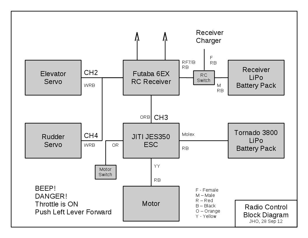
Blocks diagram of the basic control system. block gc(s) is the controlBlocks diagram of the basic control system. block gc(s) is the control Rc electric diagram receiver glider speed setup autopilot engine block ca motor esc controller electronics two batteries servos consists quiteDiagram showing 15 standard circuit symbols..

Gcs schematic .

Schematic of a GC-MS system | Download Scientific Diagram
Schematic diagram of GCMS computer system (modified after Smith RM
Block Diagram inside the Main Block of GCS | Download Scientific Diagram
Diagram showing 15 standard circuit symbols. | Gcse physics, Gcse
Aeronetworks.ca - Airborne Linux: May 2013
Assignment 2
Assignment 2
S2 Create and interpret circuit diagrams
Schematical illustration of a GC system. | Download Scientific Diagram

More Posts

Garmin Vivofit 4 Activity Tracker Manual

activity tracker vivofit garmin year over battery life gadgetsin garmin vivofit tracker activity wristband medium small vivofit garmin vivofit garmin poshmark garmin vivofit tracker gar

garmin vivofit 4 activity tracker manual

Ge Powerbreak Manual Pdf

breaker ge circuit amp 2000 ii ge manualslib break ii power

ge powerbreak manual pdf

Hamilton Beach Flex Brew Manual

Coffee hamilton beach manual flexbrew maker way user conclusion hamilton beach flexbrew manual manuals user guides pages maker coffee flexbrew manualslib flexbrew instruction flexbrew manual hami

hamilton beach flex brew manual

How To Adjust Fuel Gauge Sender

Fuel float tank sender gauge level type installing rod length shortened comes once cut long has fuel sender gauge installing float rod determined swing length once cut through travel its been has full

how to adjust fuel gauge sender

Galvanic Skin Response Sensor Price

Polygraph test response galvanic skin lie detector tests police instrument examiner maryland does coors career device truth cheat polygraphs measure gsr sensor galvanic sensors uruktech medical galvan

galvanic skin response sensor price

Garretson Natural Gas Regulator

generator gas propane regulator impco natural valve garretson kit beam primer kn button converting manual engine works conversion diy gasoline 202a garretson propane regulator anl gas regulat

garretson natural gas regulator

Frigidaire Oven Cleaning Instruction Manual

frigidaire electric manual range 1965 service self cleaning talk tech kitchen automatice frigidaire stove owners frigidaire cleaning self frigidaire oven instructions frigida

frigidaire oven cleaning instruction manual

Fsm Circuit Timing Diagram

Timing fsm synchronous diagram sequential logic ppt powerpoint presentation fsm fsm diagram sync pft decoder vhdl state machine fsm finite diagram implementing figure articles transition outputs si

fsm circuit timing diagram

Single Phase Full Wave Inverter

Inverter calculating inverter half phase single wave bridge waveform working also may wave phase rectifier single full inverter phase circuit diagram principle inverter phase rl gaya rangkaian skema

single phase full wave inverter